|
 About Us
Read
about PMP's history and philosophies
What We Sell
View a full listing of products sold by PMP
Shopping at PMP
An
overview of shopping at PMP
Newsletters
Come Visit Us
We
are always happy for modellers to drop in and shop. Here are directions,
give us a call to let us know you're coming.
Agents/Suppliers for:-
|
|
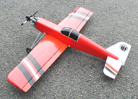
Kerfuffle
1295mm Crash
Resistant Sports Aerobatic Power Model for .25 - .46 cu in. Engines
Designed
by Stan Yeo
Produced
by PHOENIX MODEL PRODUCTS
Introduction
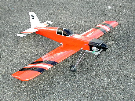
Kerfuffle
is a crash resistant sports aerobatic power model designed for the sports
flyer looking for something with a plenty of performance that is significantly
more robust than the average wood / foam model. It is more than capable
of completing the BMFA 'B' certificate schedule and plus some! Since its
introduction to this country EPP (expanded polypropylene) has revolutionised
learning to fly radio control models, particularly gliders. Now it is
the time for power flyers to enjoy the benefits of its quick build time
and less stressful flying. Few EPP models are pleasing to look at or build
but they do allow modellers to enter the hobby in a less painful way.
The accessories supplied in the kit are as used in the prototypes and
more than up to the job they have to do. Likely damage in the event of
a serious mishap are a broken propeller, engine mount and possibly wing
dowels so it is worth having spares. Wing dowel breakage can be avoided
if a thicker dowel is used but we prefer the dowels to break, which are
easily replaceable if not glued, rather than some other part of the structure
which would be more difficult to repair. Items not supplied in the kit
include adhesives, radio control equipment, engine, glues and coloured
vinyl tape (used to protect covering from ultra violet light and decorate
the model). We can supply all of these items at competitive prices so
please ask if you need them.
Tools
/ Materials Required
A limited
range of tools / equipment is required to build Kerfuffle. These include
a Scalpel with a supply of spare blades, 180 grade Wet & Dry abrasive
paper, a film iron for covering (optional), a long bladed knife (sharpened
broken hacksaw blade - it is flexible!) plus a soldering iron. Glues used
are Impact Adhesive such as Evo-Stik or Bostik, 12 minute Epoxy and thin
Cynoacrylate (superglue). Impact adhesive is used for all joints unless
otherwise stated. Also required is Spray Adhesive for gluing the EPP foam
to the fuselage sides and priming the EPP before covering with the CW
tape (Cross Weave Filament tape) and the coloured vinyl mentioned previously.
All items are available from us including the R/C equipment at competitive
prices.
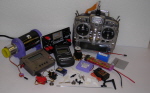
R/C
Equipment
A 4 channel
radio control set with 4 standard size servos and rechargeable batteries
on 35mHz is needed to fly Kerfuffle. An entry level set such as the Hitec
Laser 4/6 and the Futaba Skysport 4/6 are more than adequate.
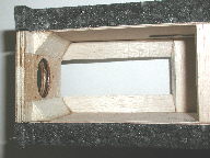
Building
the Fuselage
- Lightly sand the fuselage sides with 180 grade wet and dry to remove
ply release agent. Remove dust with a small brush or vacuum cleaner.
- Drill wing dowel holes (5mm) and control rod holes (3mm) in ply fuselage
sides.
- Mark fuselage sides LEFT and RIGHT. Cut 2mm from front of RIGHT side
to allow for built in right thrust (see plan).
- Using a small round file elongate the control rod holes at an acute
angle so the pushrods exit the fuslge close to the sides. The holes
are a long way back from the tail to allow for the exit position of
the pushrod from the EPP foam!
- Clad fuselage sides with EPP (may not be single pieces) by spraying
both surfaces with Spray impact adhesive. Allow solvent a few minutes
to evaporate before joing together. Ensure foam is attached the the
outside of each side!
- Trim EPP to size ensuring that the edge is at right angle to the
ply sides.
- Using the non-bent end of one of the control rods heat the last 10mm
to red heat and use it to 'melt' a hole in the foam at the previously
mentioned acute angle for the pushrods. TAKE CARE. The foam melts very
quickly! 'Drill' some test holes in the scrap wing material. Repeat
procedure for wing dowel holes.
 Cover plan with 'clingfilm' and build fuselage upsidedown above plan.
Insert wing dowels and use set square to true up fuselage sides. NOTE:
Plan is drawn looking down on the top of the fuselage so the side thrust
will be the opposite way to that shown on the plan due to the fuselage
being built upsidedown. The RIGHT fuselage side is positioned towards
the bottom of the plan!
Cover plan with 'clingfilm' and build fuselage upsidedown above plan.
Insert wing dowels and use set square to true up fuselage sides. NOTE:
Plan is drawn looking down on the top of the fuselage so the side thrust
will be the opposite way to that shown on the plan due to the fuselage
being built upsidedown. The RIGHT fuselage side is positioned towards
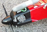
the bottom of the plan!- Use Superglue to glue fuselage blocks and triangular undercarriage
mount supports to sides. Picture shows sides without EPP foam (old procedure).
- Glue 6mm strip to front of tailskid (two pieces of 1.5mm ply laminated
together using Superglue) and fit tailskid. Caution it should be flush
with tailplane seat!
 Using template on plan drill holes in engine bulkhead for engine mount
fixing bolts and insert 4M pronged 'T' nuts to rear face (use hammer.
Before drilling check holes align with mount. Note engine mount is offset
to lefthand side to make allowances for right side thrust.
Using template on plan drill holes in engine bulkhead for engine mount
fixing bolts and insert 4M pronged 'T' nuts to rear face (use hammer.
Before drilling check holes align with mount. Note engine mount is offset
to lefthand side to make allowances for right side thrust. - Superglue 12mm triangular strips to engine bulkhead. Make allowance
when positioning for sidethrust. The angles of the bulkhead to the fuselage
sides are NOT right angles!
- Remove from plan and fit engine bulkhead. Using Superglue glue 12mm
triangular strip to tailplane.
- Superglue Fin to tailplane / triangular strip. Fit second triangular
strip to opposite side of fin. Check Fin is at right angle to tailplane.
If fin leans one way slit triangular strip on inboard side and insert
a thin piece card / plywood of appropriate thicknes to correct problem.
When satisfied use Superglue to fix.
- Epoxy Tailplane in position ensuring it is square with the fuselage.
Use a ruler or piece of string to check the distance from the tip of
the tailplane to a central point on the fuselage is equal.
- Using Impact adhesive fit topdecking and canopy. Trim canopy to shape
using hacksaw blade knife and fine slicing cuts. Fit front EPP fuselage
top.
- Remove 1.5mm strip from bottom of tailplane and fin to form rudder
elevator hinge line as per the plan. Mark centreline of tailplane and
draw a parallel line 2mm either side of line. Ensure lines are square
to hinge line.
- Fit elevator joiner and relieve rudder to accommodate joiner.
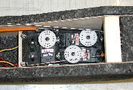
- Fit the rudder Elevator and throttle servos across the fuselage on
balsa beams. If you have a servo mounting tray use this along with balsa
beams as it is a much neater job.
- Determine which side the rudder and elevator controls rods will exit
the fuselage for the controls to operate in the correct sense and fit
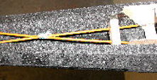
the rudder and elevator pushrods. Tie control rods together to prevent
control 'blowback'(see below).
- Cut fuselage bottom to length, make allowance for block behind the
wing and fit.
- Using Superglue or acrylic varnish 'fuelproof' the engine bulkhead,
inside of tank compartment and tailskid (do it outdoors!).
- Mark position for holes to mount undercarriage clamps and drill 1.5mm
pilot holes. Fuelproof holes with Superglue.
- Glue undercarriage mounting in position.
- Sand flush the joints between the engine bulkhead and the undercarriage
mount and trim the EPP to a radius on the corners. Use 180 grade Wet
& Dry to finish.
- Lightly spray fuselage with Spray impact adhesive and when dry cover
with CW Tape lengthwise starting under the tailplane on each side and
working around, overlapping each strip 8 - 10mm. Use a low temperature
iron to 'shrink' the tape around the compound curves.
- Cover model with coloured vinyl tape to the colour scheme of your
choice. Use low temperature iron to shrink tape around compound curves.
- Cut dowel holes and fit. Fit undercarriage using self tap screws.
- Fit fuel tank. Ensure that 'clunk' is just clear of the end of the
tank and free to move. The fuel fill line is the pipe that goes to the
bottom of the tank. Tape around fuel tanks pipes on outside of engine
bulkhead to minimise ingress of fuel etc.
- Fit engine to mount using self tap screws. Fit mount to fuselage.
Drill hole for throttle control rod using pointed piece of 10swg (3mm)
piano wire ensuring that it will not foul the fuel tank (remove fuel
tank before drilling hole!).
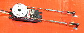
- Install control cables and set up controls. Note how the rudder pushrod
is fitted. Set up throttle so that on a low trim setting the engine
will cut. Note engine throttle trims normally only operate on
 computer transmitters when the throttle control stick is in the low
throttle position).
computer transmitters when the throttle control stick is in the low
throttle position).
- Fit engine cowl. Please note the guidelines on the cowl are for MDS
28/38 engines. Cowl is held in position using Selotape Diamond.
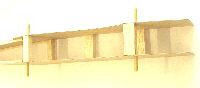
Building
the Wings.
- Lightly sand wing surfaces and remove dust.
- Fit hardwood rear spar and cut to length. Hold in position using
masking tape whilst adhesive dries.
- Remove foam from mainspar slot. Mark centre of spar brace and attach
to mainspars. If required up to 10mm of dihedral can be incorporated
when joining the wing spars. Carry out dummy assembly of wing. Note
due to unavoidable shrinkage of foam it may be necessary to trim wing
root joint to obtain a flush fit.
- Epoxy mainspar to one wing panel aligning top of spar with top surface
of wing. Use masking tape to hold wing together whilst epoxy sets.
- Fit second wing panel to spar and join with first wing panel as before.
Use wood filler or bath sealer to fill gaps in main spar slots.
- Masking tape 12mm balsa sheet centre section TE in position and mark
location of aileron torque rods. Note when assembled there is a gap
of 20-22mm between the torque rods.
- Cut out recesses in trailing edge to accommodate torque rods and
epoxy in position taking care not to let epoxy 'freeze' torque rods
in their tubes.
- Shape trailing edge to follow wing section but keep TE at least 1.5mm
thick at edge.
- Cut out a cardboard rectangle slightly smaller than the base of the
aileron servo. Use this template to cut a rectangular hole behind the
mainspar for the aileron servo. The aileron servo should be a tight
fit in the hole. Check servo fit and then remove. Use bottom of block
removed to fill in gap under aileron servo.
- Spray wing with adhesive and allow to dry.
- Cover wing with CW tape starting at TE as per instructions shown
on plan. Overlap covering by 100mm either side of wing joint and each
strip by 8 to10mm.
- Use 180 grade Wet & Dry sanding block to bevel nose of ailerons.
Lightly sand top and bottom surfaces and remove loose dust using a vacuum
cleaner.
- Cover aileron using self adhesive vinyl tape or the sticky back plastic
covering used earlier.
- Cut Mylar strip into 13mm wide pieces to make aileron hinges. Cut
hinge slots (3 per side) in ailerons and wing TE. Use small drill at
start and end of slot to assist in cutting slot for Mylar hinge.
- Lightly grease torque rods and Epoxy ailerons to them using masking
tape around back whilst epoxy sets to hold in position. Fix Mylar hinges
using Superglue (Cynoacrylate).
- Assemble aileron push rods as per plan ensuring control surfaces
are neutral with aileron servo centralised.
Flying
The following
notes are in no way comprehensive but form the basis of an elementary
check-list. It is strongly recommended that you join a local club and
seek their help and guidance. Do not attempt to fly without third party
insurance. The British Model Flyers Association (BMFA) Tel. No. 0116 244028
will be able to provide you with details of your local club and provide
third party insurance at nominal cost.
Preparation
- Check all controls operate in the correct sense: 1. The Elevator
goes down when the control stick is pushed i.e. towards the top of the
case.
- The Rudder moves to the right when the control stick is moved to
the right
- The right Aileron goes UP when the control stick is moved to the
right.
- The Throttle is fully open when the throttle stick is pushed forward
towards the top of the case.
- Check control movements / balance point:
- Ailerons +/- 12mm
- Elevator +/- 12mm
- Rudder +/- 25 degrees
- Balance Point 75mm +/- 5mm (Mainspar)
- Check ALL engine bolts and screws for tightness, particularly if
the engine is new. I personally nearly lost the carburettor screws during
ground running checks!
- Balance wing. Insert slivers of lead sheet or screws into 'light'
wing.
- Assemble the model using 100mm rubber bands. Check the balance point
is 65mm +/- 5mm back from leading edge (fuel tank empty). Adjust as
necessary by adding weight to the tail or placing weights underneath
fuel tank.
- Check flying surfaces for warps (twisting). Warps can be removed
in the wings by twisting the wing in the opposite direction and re-smoothing
the covering using a warm iron.
- If fitting a higher powered engine i.e. an MDS 38 it is strongly
recommended that 3mm carbon rod is inserted in the flute of the Tailplane
and Fin to prevent twisting during high stress manoeuvres. One just
in front of the hinge line and a second just back from the leading edge.
Wrap the carbon rod in masking tape to stop it 'rattling' around.
- It is recommended that the engine cowl is not fitted for initial
test flights just incase there is a problem and the model crashes. It
also aids engine cooling if it is a new engine that is being run in.
With a new engine observe the manufacturers running in procedure. Run
the engine rich and do not hold peak RPM for more than a few seconds.
At the first signs of distress throttle back. Recommended propellor
for MDS 28 9inx5in or 9inx6in. For the MDS 38 a 10inx5in is recommended.
A finer pitch propellor will give the engine static thrust for takeoff
thrust and not load the engine quite once the model is airborne.
- After flying please thoroughly clean oil and fuel residue from the
model. Oil, if allowed, will seep under the covering and desolve the
tape adhesive over time making it more difficult to refurbish the model
should it become necessary. Window cleaning fluid or or car screenwash
do a good job.
- At the start of each flying session it is recommended that the engine
is run rich, on full throttle, on the ground for a few minutes to clear
any oil residue from the tank and carburettor etc. Failure to do this
could result in the engine cutting once airborne.
Flying
- Some common problems
Again these
notes are deliberately brief. It is not possible to cover all aspects of
model flying in the building instructions so if you are inexperienced please
seek help.
- Model noses over on take-off. Balance point could be too far back.
Hold in full up elevator until model starts to lift-off then promptly
return elevator to neutral. Failure to release the elevator could result
in the model tip stalling into the ground immediately after takeoff.
- Model does not track straight on the ground or is difficult to keep
tracking in a straight line. Possible causes misaligned undercarriage,
Rudder control surface out of trim or model not being directly into
wind for takeoff or not applying enough up elevator on takeoff run.
Check U/C alignment, neutralise rudder ensure model is taking off into
wind. If problem still persists put toe-in on undercarriage and or use
rates to reduce the sensitivity of the rudder on take-off but restore
full rudder control when airborne.
- Model wants to climb continuously but when the throttle is closed
or the engine cuts model dives. Not enough downthrust on engine or balance
point too far back. Check balance point and move forward if necessary.
Pack up back of engine with washers and try again. If still insufficient
pack engine mount.
- Model 'tip' stalls i.e. drops a wing when slowed down. Possible cause
a warped wing, or trying to fly too slowly.
- When looping into wind, wings level, the model 'corkscrews' out of
the loop. Most likely cause, other than a warped wing, rudder not trimmed
to neutral. Note direction of screw and adjust rudder trim. Try again
ensuring model is pointing into wind and the wings are level throughout
the loop. Repeat until satisfied.
- Model dives during a roll. Insufficient down elevator during the
'inverted' phase of the roll or lack of speed. Ensure model has sufficient
speed to carry out the roll and start the roll with a slightly nose
up attitude.
- Model dives in a turn. Most likely cause not enough up elevator applied
in the turn. Watch the fuselage during the turn, keep it level.
Finally should you require further assistance or advice please contact
us either by letter, telephone, email or visit our website (http://www.phoenixmp.com)
where you can find lots useful information and our full catalogue.
Happy flying
Stan Yeo
Kerfuffle
030825
|
|