|
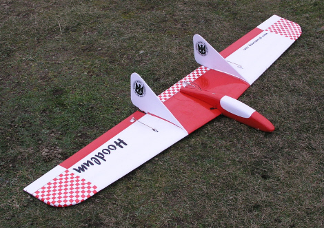
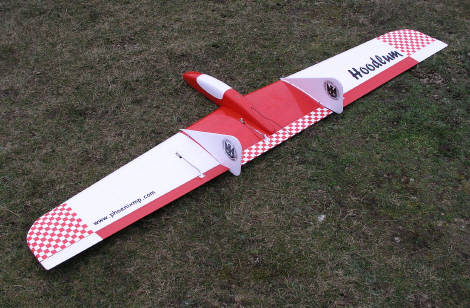
Hoodlum
Crash Resistant
60in EPP Pylon Racer / Sports Aerobatic Slope Soarer
Designed
by Stan Yeo Produced by PHOENIX MODEL PRODUCTS
Introduction
The
Hoodlum is a flying wing with a difference. The ailerons and elevator
do not share control surfaces and consequently do not require a control
mixer but if you do own a computerised transmitter there are a number
of additional control options available such as Crow Braking to aid landing
in tight areas or when flying with full ballast. Also the elevator can
still be coupled with the ailerons to improve performance in 'looping'
manoeuvres (inside and out). With a separate elevator, control response
is more progressive. This is accompanied by a small reduction in induced
drag at the wing tips. Like other models in the series the Hoodlum is
capable of a wide range of aerobatic manoeuvres including inside and outside
loops, horizontal eights (like a Cuban Eight without the half roll in
the middle), continuous inverted flight and several consequetive rolls
not to mention a very good turn of speed with or without ballast. There
is provision to carry up to 12ozs (340 grams) of lead in wing mounted
ballast boxes to give added bite in strong winds and trade excess lift
for speed. As with all EPP models, building time has been kept to a minimum;
typically a quarter to a third that of an equivalent wood foam model depending
on the skill and care taken.
Tools
/ Materials Required
The only
tools required are a modelling knife and spare blades, 180 grade Wet &
Dry sanding block, a set square, soldering iron and a hand drill with
a 5mm bit. Glues etc. required are spray impact adhesive (Stikatak), runny
super glue, 12 minute epoxy and Sellotape Diamond plus 'top covering'.
Please observe safety precautions for the glues!
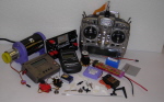
R/C
Equipment
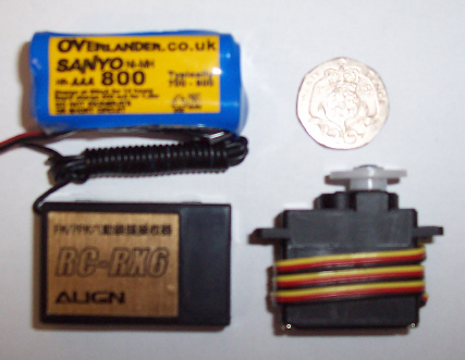
The R/C equipment
used in the prototypes consisted of three metal gear micro servos (HS81MG
/85MG/ Futaba S3150) a AAA size square Rx battery pack plus a JR R700
/ Align 6 / Futaba 147F / Hitec Slimline Rx along with a switch harness
and two servo extension leads. All the items are available from PMP at
competitive prices.
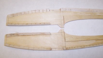
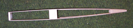
Building
the Fuselage
- Lightly
sand the fuselage sides, top and bottom with 180 grade wet and dry to
remove the 'release' agent. Remove dust with a small brush or vacuum
cleaner.
- Mark
position of 4.5mm distance pieces (2 off) to fuselage sides ensuring
you have a left and right side!
- Superglue
4.5mm sq. strip and triangular nose strips to fuselage sides (not shown
in picture below - error!).
- Superglue
wing seats in position.
- Superglue
nose former (B1) and the other two 4.5mm distance pieces (B2/3) to one
fuselage side ensuring they are all perpendicular (use set square) Check
dowel former can be slid in position.
- Fit balsa
block at rear of fuselage.
- Join fuselage
sides together over plan checking that the fuselage sides are correctly
aligned using a set square.
- Cut 1.5mm
fuselage top to length and superglue in position.
- Repeat
Step 9 above for fuselage front bottom front allowing for wing dowel
plate.
- Fit 1.5mm
ply bottom to rear of fuselage.
- Cut /
Sand ply top and bottom to size.
-
Fit switch harness to top of fuselage. Take care not to mount the
switch to far forward so the it interferes with fitting the Rx battery
and receiver. Remove switch after fitting.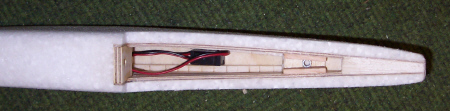
- BUILD
WING
- Construct
Wing Nut block assembly as per plan. Slide into and hold in place and
hold in position using scrap foam rubber. Slide into position the 6mm
ply Wing Dowel plate.
- Fit the
wing to the fuselage and mark position of wing dowel hole on dowel plate.
Tip - wet end of dowel tube with felt tip pen to leave impression on
dowel plate. Ensure dowel hole is in middle of dowel plate and drill
dowel hole.
- Superglue
dowel former in position. If necessary, slide former 'in & out' or rotate
back to front as necessary to compensate for any inaccuracies in drilling
dowel hole.
- Fit triangular
strip to front of former (see plan).
- Fit wing
to fuselage and locate position of wing nut assembly.
- Glue
nut assembly in position.
- Glue
EPP sheets to fuselage sides using spray adhesive (spray both surfaces).
Allow a couple of minutes for solvent in adhesive to evaporate before
fitting EPP to fuselage. Allow the EPP to extend past the nose former
by at least 12mm (see plan). Also remember this is a ONE shot operation!
- Trim
the EPP to shape of fuselage using White Spirit to lubricate knife.
The best tool for this operation is one made from a broken piece of
hacksaw blade approximately a 75mm long. Grind the teeth off without
getting the blade so hot that it loses its temper and goes soft. Sharpen
blade on a whetstone or oilstone so that you could almost shave with
it! The advantage of this blade over commercial blades is that it is
flexible allowing the 'handle' to be bent out of the way when cutting
the EPP to achieve an acute cutting angle.
- Glue
8mm thick EPP to fuselage top aligning Fin slot in EPP with Fin slot
in fuselage again extending beyond nose former as per Step 20.
- Glue
8mm thick strip of EPP to fuselage bottom at nose. Extending beyond
nose former.
- Glue
approximately 90grams of roofing lead to front of nose former in cavity
formed by EPP sides. This is typically 2mm thick and equates to 5/6
layers of lead. Flatten lead before fitting. DO NOT GLUE. Roofing lead
is available from a scrap yard at reasonable cost. Trim EPP in front
of nose weight to provide flat surface on which to glue EPP nose-block.
- Fit nose
block and shape fuselage i.e. round corners using sharp knife and 180
grade wet & Dry (use dry!).
- Because
the wing mounted ballast boxes are forward of the Balance Point adding
ballast moves the balance point forward. To compensate for this some
of the nose weight is removed. This requires a small hatch underneath
the nose weight. Remove a rectangular piece of EPP and replace it with
balsa block. Shape balsa insert.
- Cover
fuselage using CW tape. Overlap each strip by 6 - 10 mm or 1/4 to 3/8
inch. Use Film Iron to remove wrinkles around compound curves. Temperature
required for this operation is fairly critical. Do not dwell in one
spot too long to avoid damage to the foam. Use white spirit to lubricate
cutting knife. Fit 6mm square strip to base of Fin at front.
- Top cover
the fuselage with either coloured vinyl tape or an iron-on film such
as Profilm (highly recommended).
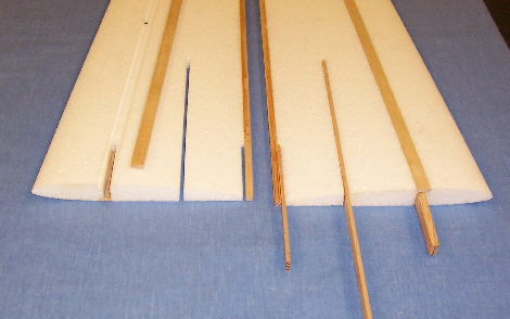
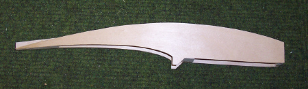
Building
the Wings.
- Lightly
sand wing surfaces and remove dust as before. Trim and sand spar slots
to accommodate mainspars. This is best achieved using a very sharp knife
and a spar length straight edge (Tip - stick 180 grade wet & Dry to
under surface for grip) plus a short length of 10mm thick ply fitted
with Wet & Dry along one edge for final sanding of spar slot. Unfortunately
CNC cutting tapered wings with spar slots results in a tapered spar
slots due to the way CNC cutters work.
- Tip -
When adjusting spar slots tape a straight edge to trailing edge of wing
to ensure TE remains straight.
- Remove
waste from wing bracing slots.
- Fit top
wing spars (the thick ones) using Epoxy keeping spar bracing slots free
of Epoxy. Place packing tape along spars, place wing on a flat surface.
Hold flat with weights until epoxy set.
- Repeat
Step 4 for bottom spars.
- Trim
spars to length.
- BUILD
BALLAST BOXES
- Fit 6mm
sq trailing edges using epoxy again keeping bracing slots free of epoxy.
Use masking tape to hold spar in position whilst Epoxy sets. Trim to
length.
- Dry assemble
wing to check that wing roots mate with a straight trailing edge. Adjust
as necessary.
- With
wing upside down fit wing brace. Note once again the trailing edge should
form a straight line i.e. not be swept back or forward.
- Fit rear
spar brace and trim to size when epoxy set.
- Fit rear
wing brace using epoxy.
- Manufacture
Elevons and wing centre by laminating 0.8mm ply and balsa trailing using
spray impact adhesive. Place under weight until adhesive has properly
set.
- Glue
centre section to wing observing wing reflex (apparent up elevator).
Refer to wing seat on fuselage.
- Fit 0.8mm
ply ends to centre section and one end of each Elevon.
- Sand
wing tips to shape and trim Elevons to size. Sand to shape.
- Epoxy
balsa block in position at wing join. Bottom of block should be flush
with bottom surface of wing.
- Trim
top surface of block to shape of top surface of wing. DO NOT trim bottom
of block.
- Locate
centre of balsa block and centre of wing leading edge. Drill hole for
5mm diameter brass tube the houses 4.5mm diameter hardwood wing locating
dowel.
- Epoxy
wing dowel tube in place. Mark centre of tube hole on 6mm ply dowel
locater in fuselage. Use felt tip pen to assist in this.
- Manufacture
a long drill using 4.5mm diameter piano and drill dowel hole in 6mm
ply.
- Drill
hole for M5 wing bolt in wing and ply bolt plate. Do not drill through
rear spar!
- Fit 1.5mm
ply wing bolt reinforcing plate using superglue.
- Shape
wing tips.
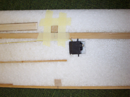
- Mark
position of wing servos (plan drawing is NOT full size. Position of
servo is dependant on servo lead length. Allow 30mm from end of plug
to servo lead exit from wing for connecting to receiver extension lead
when fitting wing. Note servo arms both point outboard of wing.
-
Cut rectangular hole for servo in wing ignoring servo mounting lugs.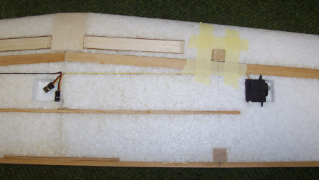
- Cut slot
in EPP for servo lugs and fit servo so that it is flush with top of
wing. Note gap between top of servo and bottom of wing. From block of
EPP removed for servo from wing slice off the required amount and fit
in this void.
- Centre
servos (see Prepare to Flap article on website) and rotate output arm
so it is flat to the wing in preparation for covering wing. Cover servo
with masking tape.
- FIT FIN
MOUNTING BLOCKS.
- Spray
wing with spray adhesive and cover wing with CW tape. For torsional
rigidity cover the wing with CW tape diagonally. There is no need to
wrap around rear spar but do overlap by 5 - 10mm at leading edge. For
smooth finish do not overlap CW Tape. Use film iron to remove wrinkles
at tips.
- After
covering fit aileron servos. Cut vertical slot in wing to hide servo
leads.
- Cover
wing with either coloured vinyl tape or an iron on polyester film (NOT
polypropylene it stretches!). This is necessary for two reasons, one
to decorate the model and secondly to protect the CW Tape from the effects
of ultra violet light. If film covering roughen surface of CW Tape and
lightly spray with impact adhesive.
- Cover
control surfaces in an iron on film in chosen colour. DO NOT use CW
or vinyl tape.
- Hinge
control surfaces using Sellotape Diamond as shown on the plan.
- Fit control
linkages and adjust to obtain required throws (see flying section).
- Unless
you are flying in high risk mid-air situations DO NOT replace the plastic
mini-snaplinks with metal devises as in the event of a mishap the plastic
snaplinks will break thereby reducing the risk of damage to the aileron
servos.
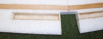
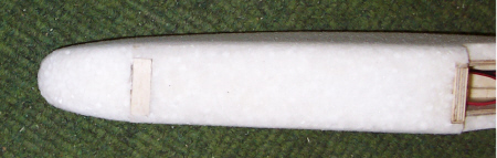
Building
Ballast Boxes
- Remove
foam from ballast box cut-out from wing.
- Construct
a distance piece that will hold the ballast box sides in place whilst
the glue sets. Again it should be a snug fit and not a force fit. Cover
in Sellotape / cling film to prevent it sticking to box sides during
assembly.
- Cut 1.5mm
ply sides to size and number them.
- Using
the distance pieces glue ballast box sides to wing.
- Superglue
balsa ends and top in position. Sand to shape.
- Fit ply
hatches. Adjust distance pieces so that when covering the wing the hatch
cannot drop down into the ballast box.
Fitting
Fin Mounting Blocks
- From
the wing join at wing root measure 200mm outwards towards wing tip on
both wings.
- Using
set square draw a line at right angles to rear spar across the wing.
This is the centre of the Fin.
- Cut rectangular
holes thro' the wing the same size as the 16mm square balsa Fin Mounting
Blocks aligning the centre of the block with the centre line of the
Fin.
- Epoxy
the above blocks in position and sand to the wing contour. Note the
grain should be vertical.
- With
the aid of the set square mark the centre of the mounting blocks and
drill VERTICAL holes the same size as the 4 mm plastic tube used to
house the 12 gauge wire to secure the Fin. DO NOT to glue the wire in
position.
- Depending
on how secure the plastic tube is in the mounting blocks will depend
on whether you glue them in using Superglue or 2 part Epoxy.
- Using
a sharp pointed rod of the same or slightly smaller diameter poke holes
in the base of the Correx Fin to accommodate the 12g mounting rods.
- Remove
the Fins and 12g rods for covering the wing.
Flying
To achieve
the design performance of any model care must be taken in setting up the
controls and balancing the model both laterally (wing tip to wing tip)
and longitudinally (nose to tail). The Hoodlum is no exception. Control
movement must be symmetrical i.e. the same for both Elevons.
Set the
controls to give the following movements for initial flights:
Ailerons
+/-18mm Elevator +/-15mm
Elevator
(Ailerons) +/-5mm
Reflex align
controls surfaces with base of Fin
Balance Point
75mm +/- 3mm from LE at back of dowel former.
- Adjust balance
point to within recommended limits. This can be done by taping a hexagonal
shaped pencil along the bottom of the wing at the balance point and
resting the model on a flat surface. Prototypes required a small amount
of additional nose-weight to that fitted in the nose.
- For competition
flying i.e. 60in EPP pylon racing, a slightly rearward balance point
was found to be the optimum. It is recommended that initial flights
are carried out at the mid balance point and adjusted to suit your style
of flying. See Item 9.
- Check than Fin
is perpendicular to wing. Adjust wing seat as necessary.
- Launching the
Hoodlum is easy. Place the thumb and second finger either side of the
fuselage just in front of the wing leading edge. The forefinger is placed
on the underside of the wing. This is important as the forefinger ensures
the model is launched in a level attitude and stops you pulling the
nose down and launching the model into the ground! The transmitter is
naturally held in the free hand.
- Remember all aerobatic
manoeuvres require energy to perform them. If the model has insufficient
speed it will fall out of the manoeuvre or perform it half-heartedly.
Vertical or near vertical dives are not an efficient way to build up
speed, 20- 30 degree dives are much more efficient. Hence the need for
progressive elevator movement. Avoid sudden control inputs. In most
cases all they do is scrub off speed and lose height but they could
also result in a violent 'flick' roll. Try to fly smoothly with the
minimum of control input as not only do the manoeuvres look better but
you will be able to perform more of them before having to regain height.
Try stringing manoeuvres together, paying particular attention to positioning.
Be creative and set yourself targets for each flying session.
- If the lift is
very good or you are having difficulty penetrating into wind try ballasting
the model. This will increase penetration and help the model maintain
speed through manoeuvres. Note when adding ballast it will be necessary
to remove some of the nose weight (using the hatch) to counteract the
effect the effect of the ballast moving the balance point forward.
- We have found
the optimum ballast to be about 200 grams. Over-ballasting any model
will lead to a degradation in performance, often accompanied by a tendency
to tip stall if flown too slowly or the elevator is used zealously.
- The suggested
control settings are a starting point and can be adjusted to suit your
personal tastes. An indication that the balance point is about right
can be gauged by the amount of down elevator required for smooth inverted
flight and how the model recovers naturally from a dive i.e. sticks
in neutral and no pilot input.
- If you are using
a computerised transmitter program in positive (JR) Exponential on the
Aileron and Elevator controls. This will 'soften' the controls around
the neutral position and facilitate smoother flying particularly on
the elevator control.
- Hoodlum will take
a lot of punishment. It is excellent for building confidence and will
add another dimension to your flying but please remember if you take
a big enough hammer to anything it will break. The CW tape used for
covering also degrades in ultra-violet light so store the model in a
relatively cool place away from direct sunlight.
- The MH64 wing
section is very efficient and performs well in light lift so with good
ballast selection Hoodlum will cope with almost any wind / lift conditions
you are prepared to fly in.
- Finally should
you require further assistance or advice please contact us either by
letter, telephone, email or visit our website (http://www.phoenixmp.com)
where you will find useful information on sloping etc.
Hoodlum
Design Features
- It uses the highly
efficient MH64 wing section.
- It has a slim,
EPP clad, ply box fuselage. Not only is the fuselage extremely strong
but it has considerably less volume than many of its contemporaries.
Fuselage volume has a large impact on a model's performance. The more
air that is displaced the higher the drag!
- The Hoodlum is
a two piece model with detachable fins. The wing is attached to the
fuselage via an easily replaceable M5 nylon bolt and a 5mm hardwood
dowel (housed in a brass tube). These are designed to shear in the event
of a 'mishap thereby minimising any resultant damage.
- The hardwood mainspars
extend all the way to the wing tip. This not only stiffens the outboard
section of the wing but offers protection to the control surfaces should
the model land on a wing tip.
- The top spar is
thicker than the bottom spar. This significantly strengthens the wing
as most wing failures in flight are due to the top surface failing in
compression.
- The thin balsa
control surfaces are laminated with 0.8mm ply to add stiffness and make
them more 'ding' proof a feature not normally seen on the type of model.
- The easily accessible,
inbuilt ballast boxes, allow quick change of ballast between flights
to take advantage of changing flight conditions.
Happy flying
Stan
Yeo
Hoodlum
060108
|