|
 About Us
Read
about PMP's history and philosophies
What We Sell
View a full listing of products sold by PMP
Shopping at PMP
An
overview of shopping at PMP
Newsletters
Come Visit Us
We
are always happy for modellers to drop in and shop. Here are directions,
give us a call to let us know you're coming.
Agents/Suppliers for:-
|
|
BAe
Hawk
1190 mm
Span
EPP Power
Scale Slope Soarer
Designed
by Stan Yeo
Produced
by PHOENIX MODEL PRODUCTS
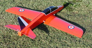
Introduction
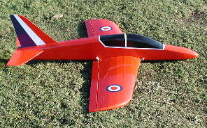
The BAe Hawk
is a stylish crash resistant character scale EPP slope soarer designed
for the sport flyer looking for something different. It will fly in relatively
light winds up to very strong winds with added ballast. Whilst the inverted
performance is limited this is more than compensated for by its manouvreability
and docile handling characteristics which also make it suitable as an
aileron trainer. The BAe Hawk is used as a fast jet trainer in the RAF
and the USAF as well as being the aircraft flown by the world famous RAF
Red Arrows aerobatic team. It is also used by a number of countries as
a ground attack aircraft. The Hawk is so fuel efficient that with full
fuel load it can fly around the coast of the United Kingdom! Building
time is anything from 10-15 hours depending on the care taken and the
finish required i.e. whether decorated using coloured vinyl tape or as,
like the protoype, covered in an iron film such as Easycoat.
Tools
/ Materials & Adhesives Required
The only
tools / materials required are a modelling knife with spare blades, a
pair of sharp scissors, 180 grade Wet & Dry sanding block and a soldering
iron. Glues used area impact adhesive such as Evo-Stik or Bostik All Clear
Adhesive for EPP foam joints. Two part Epoxy for fitting the wing spars
and wing braces plus joining the wings. Runny Superglue for gluing the
balasa blocks and a can of Spray Impact adhesive such as Stikatak for
fitting the ply doublers. Sellotape Diamond for fitting the Fin to the
Tailplane and hinging the ailerons in a two servo wing installation. The
covering material can be either an iron film or coloured vinyl tape. Please
observe all safety precautions on containers. Impact adhesive is used
for all 'foam' joints EXCEPT the mainspars and the wing brace where Epoxy
is used. Superglue is used for all wood to wood joints except wing brace.
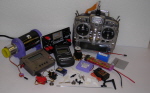
R/C
Equipment
The R/C equipment
used in the prototypes consisted of standard size servos for the elevator
and ailerons (single servo installation), HS300 size, a square 700mA nicad
pack and a Hitec / GWS mini Rx. For the twin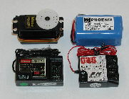 aileron servo installation any mini / metal gear micro servos can be used.
We recommend the Perkins SuperTec 3002BB minis or the Hitec HS81MG servos.
If you are using a computerised transmitter then the ailerons can also
be used as flaps and coupled with the elevator in which case a 6 channel
receiver such as the GWS 8 channel Micro Rx will be required. All the
items mentioned are available from PMP.
aileron servo installation any mini / metal gear micro servos can be used.
We recommend the Perkins SuperTec 3002BB minis or the Hitec HS81MG servos.
If you are using a computerised transmitter then the ailerons can also
be used as flaps and coupled with the elevator in which case a 6 channel
receiver such as the GWS 8 channel Micro Rx will be required. All the
items mentioned are available from PMP.
Building
the Fuselage
- Lightly
sand the fuselage and doublers with 180 grade wet and dry. Remove dust
with a small brush or vacuum cleaner.
- Glue
nose & tail sections together using impact adhesive and drill wing dowel
holes in ply nose doublers in positions marked.
- Cut 1.5mm
x 12mm hardwood strip rear fuselage / tail doubler to size.
- Glue
nose and rear fuselage / tail doublers in position using impact
adhesive.
- Drill
dowel holes in foam. Glue nose former in position. Fit B1, B2, B3 &
B4 12mm balsa blocks in position (fit wing dowels and use as a guide
to get fuselage square).
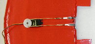
- Fit elevator
servo to 12mm square blocks. Glue blocks / servos in position with blocks
close to top of ply doubler.
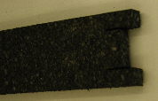
- Join
fuselage at rear using small EPP block supplied in kit.
- Dry fit
fuselage top. Pin in position and trim to shape. Do same to fuselage
bottom.
- Mark
elevator hinge line on Correx tailplane and remove strip of
 plastic on one side to form hinge line. The elevator hinge line is 6
whole flutes (32mm) forward of the trailing edge at fuselage joint.
Push fit elevator joiner in position.
plastic on one side to form hinge line. The elevator hinge line is 6
whole flutes (32mm) forward of the trailing edge at fuselage joint.
Push fit elevator joiner in position.
- Fit Fin
to Tailplane using strip of Sellotape Diamond. Glue tailplane to fuselage.
Fit fuselage top (front & rear), cockpit, nose bottom and nose block.
- Check
which side the control rod must be connected to the elevator
 servo for the controls to operate in the correct sense and plan route
for elevator control rod.
servo for the controls to operate in the correct sense and plan route
for elevator control rod.
- Install
elevator control rod. Bore hole in foam by heating the end 10mm of elevator
control rod. Drill and fit control rod. Tape control rod to inside of
fuselage using CW tape.
- Fit fuselage
bottoms checking that fuselage is not bent or twisted.
- Cover
fuselage using CW tape. In restricted areas such as the base of the
fin etc strip CW tape to 25mm wide. In high stress areas such as under
the leading edge of the tailplane and above the wing trailing edge apply
an EXTRA layers of tape for added strength.
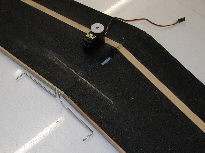
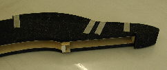
Building
the Wings.
- Lightly
sand wing surfaces and remove dust as before. Using a SHARP scalpel
and straight edge trim spar slots to size. Unfortunately due to restriction
in the CNC foam cutting machines tapered wings produce tapered spar
slots. Remove waste from wing brace slot.
- Fit 3mm
x 10mm hardwood trailing edges using impact adhesive.
Ensure that the TE is straight otherwise difficulty will be experienced
in fitting the ailerons.
- Fit top
wing spars using Epoxy, cut to length and join wings.
- Fit main
wing spar brace and bottom wing spars, again using Epoxy. Trim spars
to length and shape wing tips. Fit 3mm rear wing brace.
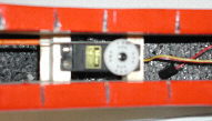
- If fitting
individual wing servos cut boxes for the servos in the wing behind the
main spar. Distance from wing joint will depend on the length of servo
lead. If servo lead is too short use servo extension leads to allow
mounting of the servo further outboard. With mini servos the servo may
protrude slightly from top of the wing.
- If using
a single servo to drive the ailerons mount the servo along
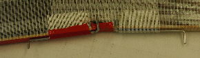 the
wing join behind the mainspars and use the torque rods supplied. Relieve
ply doubler and Block B4 to accommodate aileron torque rods to prevent
binding and any unnecessary friction. Use 50mm Cross Weave Filament
tape (CW tape) to tape torque rods to wings. the
wing join behind the mainspars and use the torque rods supplied. Relieve
ply doubler and Block B4 to accommodate aileron torque rods to prevent
binding and any unnecessary friction. Use 50mm Cross Weave Filament
tape (CW tape) to tape torque rods to wings.
- Make
a rectangular template of the aileron servo(s) ignoring lugs but allowing
for output arm and cut rectangular hole(s) in wing. Servo(s) should
be a snug fit in hole. If fitting outboard wing servos use foam block
removed to restore wing lower surface and a hacksaw blade to cut recess
for servo lugs.
- Before
covering the wing with CW tape remove the aileron servo(s)
 and prime the foam with a spray on impact adhesive (Stikatak). Hold
nozzle 40 to 50 mm away from foam and allow 10 minutes for solvent to
evaporate before covering.
and prime the foam with a spray on impact adhesive (Stikatak). Hold
nozzle 40 to 50 mm away from foam and allow 10 minutes for solvent to
evaporate before covering.
- Cover
wing with CW tape. Start by laying a strip along the TE of each wing
panel. Each strip should overlap the wing joint by 100mm each side.
This provides increased strength and stiffness at the wing joint. Work
forward, bottom first, overlapping the previous strip by 5-10mm. At
the leading edge overlap tape by 10 mm.
- Cut ailerons
to size (allow a 10mm gap between fuselage side and end of aileron.
Shape aileron leading edge (see plan for single servo operation|). The
ailerons are top hinged for twin servo installation and centre hinged
for single servo installation.
- Cover
the ailerons, starting at TE using either CW tape or coloured vinyl
tape etc.
- For single
servo aileron operation use CW tape to attach aileron torque rods to
wing and to tape ailerons to torque rods (see plan). Hinge ailerons
as per the plan using Sellotape Diamond.
- Decorate
model using stick on trim such as Protrim / Solartrim / Fablon or coloured
vinyl tape which is available from PMP. Alternatively an iron-on film
such as Easycoat can be used (Easycoat comes highly recommended and
is a polyester film with excellent shrinkage properties). To film cover
Correx surfaces it is recommended that 'spray' impact adhesive is used
in conjunction with a cool iron. BEWARE the Correx is easily distorted
by heat.
- Fit control
linkages and adjust to obtain required throws (see flying section).
Flying
- Set the controls to give the following movements for initial flights
- Elevator +/- 12mm
- Ailerons +/- 15mm
- Flaps (if fitted) +/- 7mm
- Adjust balance to within recommended limits (130mm +/- 5mm from LE).
Prototypes required 20 - 40gms of lead in the nose. Check alignment
of wing and tailplane and wing to tailplane incidence (bottom of flying
surfaces should be parallel). Laterally balance wing and check that
it is not twisted. If the wing is twisted, twist back in the required
direction and re-smooth covering tape with warm iron. If model is fitted
with flaperons check zero flap is in fact zero flap otherwise performance
will be impaired!
- Please remember all aerobatic manoeuvres require energy in the form
of speed to perform the manoeuvre. If the model has insufficient speed
it will fail to complete the manoeuvre or perform it half-heartedly.
Vertical or near vertical dives are not an efficient way to build up
speed. A 30 deg. dive is much more efficient. Avoid sudden control inputs.
In most cases all they do is scrub off speed and lose height. Try to
fly smoothly as not only do the manoeuvres look better but you will
be able to perform more of them before having to regain height.
- Pay particular attention to positioning and where others are in the
sky.
- If the lift is good or you are having difficulty penetrating into
wind try taping ballast under the balance point. This will increase
penetration and help the model maintain speed through the manoeuvres.
- The suggested control settings are a starting point and can be adjusted
to suit your personal tastes. Adjust the balance point so that when
the model is trimmed the elevator is more or less in the neutral position.
- The BAe Hawk will take a lot of punishment far more than any equivalent
wood, foam or moulded model. It is excellent for building confidence
and will add another dimension to your flying but please remember if
you take a big enough hammer to anything it will break. Store the model
away from direct sunlight in a cool place as the CW tape degrades in
UV light. Do not rest anything on the Correx tailplane as this will
deform it.
- Finally should you require further assistance or advice please contact
us either by letter, telephone, email or visit our website (http://www.phoenixmp.com)
where you will find useful information on sloping etc.
Happy flying
Stan Yeo
BAe
Hawk 020623
|
|