|
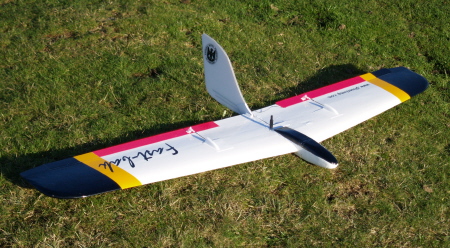
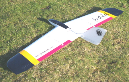
Fast-bak
Crash Resistant
60in EPP Pylon Racer / Sports Aerobatic Slope Soarer
Designed
by Stan Yeo Produced by PHOENIX MODEL PRODUCTS
Introduction

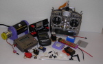
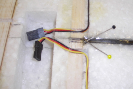
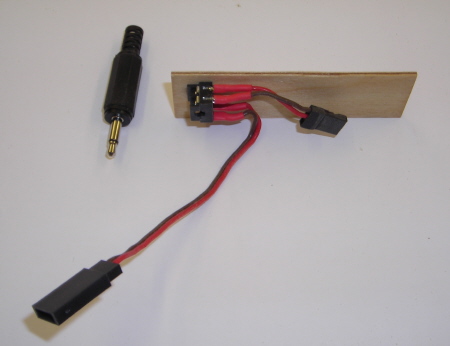
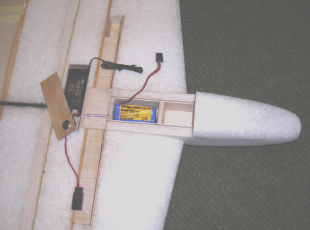
Fast-bak
is the fifth model PMP have developed for the popular 60in EPP Pylon racing
class. Needless to say each model has seen an improvement in performance
on its predecessor. Fast-bak is no exception. Not only is it faster, but
it is easier to build and more robust in the world of model on model pylon
racing. Despite its pedigree, Fast-bak is also an excellent sports model,
more than capable of performing any manoeuvre that could be expected of
a flying wing, continuous loops and rolls, sustained inverted flight and
with practice rolling circles.
As with all
EPP models, building time has been kept to a minimum; typically a quarter
to a third that of an equivalent wood foam model depending on the skill
and care taken
Tools
/ Materials Required
The only
tools required are a modelling knife and spare blades, 180 grade Wet &
Dry sanding block, a set square and soldering iron. Glues etc. required
are spray impact adhesive (Stikatak 3M77), runny super glue, 12 minute
epoxy, No Sanding Polyfilla and Sellotape Diamond plus 'top covering'
(Profilm recommended). Titebond Polyurethane glue can be used for fixing
the mainspar assembly if preferred. Please observe safety precautions
for the glues!
R/C
Equipment
The R/C equipment
used in the prototypes consisted of two metal gear micro servos (HS81MG
/85MG or Futaba S3150 Digitals) a AAA size square Rx battery pack, a JR
R700 / RS70 (highly recommended) / Futaba 147F / Hitec DC Slimline Receiver
and a switch harness or Jack Switch assembly. All the items are available
from PMP at competitive prices.
Building
the Wing
- Laminate
Elevons (0.8 mm ply & balsa TE stock) and trailing edge section
using spray impact adhesive. Glue ply to base of right angle triangle
NOT the hypotenuse (the longer face). Be properly prepared as this is
a one shot operation that can easily go wrong. After joining together
assemble in pairs to form a rectangular section and weight down on flat
surface for 24 hours (Kitchen worktop ideal, seoarate with cling film)
to allow the glue to cure.
- Using
50 mm wide masking/packing tape, place a strip along the main spar slot
cut out on the underside of the wing, taking care not to close the saw
slots.
- Remove
EPP foam from spar slots.
- Either
using epoxy or Titebond polyurethane glue, glue the 2 mm thick balsa
mainspar capping strip in position. Ensure the capping strip is flush
with the surface of the wing, sit wing in appropriate 'sleeve' and 'weight'
down whilst glue is setting. Repeat
for second wing panel.
- Again,
either, using 12 min epoxy or polyurethane glue, glue the main spar
in position. Do not use too much glue as the glue effervesces and expands
(foams) with sufficient force to push the joint apart. Keep the wing
weighted down in its sleeve until the glue sets. If using Titebond combine
operations 5 & 6.
- Fit the
4.5 mm top capping strip with glue of choice.
- Using
180 grade Wet & Dry sand capping strips flush with surface of wing.
- Fit the
spruce rear spars using epoxy. Hold in position whilst glue sets with
masking tape. We do not consider that polyurethane glue is appropriate
for this joint.
- Manufacture
mainspar extension drill as per the diagram on the plan. Note
it is important that the end of the drill is screwdriver shaped and
NOT ground to a point. Drill holes in wing for main spar
extensions.
- Remove
carbon tubes from spar extension drill.
-
Assemble main spar extensions using Superglue and glue / fit into
wing. Use extension drill to push spar extension into wing and check
that it has been is pushed fully into position.
- Dry assemble
the two wing halves. Adjust joint as necessary.
- Using
epoxy glue, glue wing joiner into one wing panel. Use masking tape to
identify middle of wing joiner so that it positioned centrally to the
main spars.
- Clear
surplus epoxy away from wing joiner and remove masking tape.
- Using
epoxy join wing halves together. Use masking tape to pull joints together
and align rear spars.
- Remove
EPP foam from rear spar slot of ballast box and fit spruce rear sub
spar. Using masking tape to pull joint together. ONLY GLUE BACK FACE
OF SPAR. Check alignment of spar and foam.
- Repeat
above for 3mm ply front spar of ballast box. ONLY PUT GLUE ON FRONT
FACE.
- Remove
EPP foam from between ballast box spars and fit 2 mm Liteply sheeting
between spars. Leave gap at one end of ballast box for loading the ballast.
Can be bottom or top.
- Cut out
receiver compartment. This is best done by making a rectangular template
of the size required, pinning it to the wing, and cutting vertically
through the wing using a pointed long bladed knife (Scalpel No 4 Handle
& No. 26 blades).
- Line
the Rx compartment with 0.8 mm ply. The base is fitted AFTER CW taping.
-
Angle Elevons at root so they form a neat joint. Measure 50mm at root
of trailing edge and cut at right angles to form centre section fixed
trailing edge (see plan).
- Superglue
fixed trailing edge in position, ply face uppermost and aligned with
bottom of wing. This will require angular adjustment.
- Face
inboard ends of elevons and ends of centre section TE with 0.8mm ply.
- Cut elevons
to length tips, as per plan (photo of Mk1 tip) leaving a gap making
an allowance for covering material.
- Chamfer
along hinge to accommodate down aileron/elevator movement.
- Find
position of wing servos plug servos by placing servo on wing between
main spar and ballast box. Stretch servo lead inwards towards wing joint.
Take end of lead past wing join until there is sufficient lead to plug
into the receiver.
- Plug
servos into receiver. Place receiver in receiver cut-out in wing. Position
servos between mainspar and rear sub spar. Drag servos towards the wing
tip until lead is taut but there is still sufficient lead to plug and
unplug servo from Rx in Rx box. Mark the position of the servo nearest
to centre of wing. This will be the distance both servos are mounted
from the centre of the wing.
- Make
a slightly smaller rectangular template of the servo (include servo
arm). Pin template to wing in allotted position and cut full depth rectangular
hole in wing 'a la' receiver box.
- Cut recesses
for servo lugs and servo lead/grommet and fit servo minus servo arm,
flush with surface of wing.
- Turn
win over. Study gap between servo and wing surface from foam block remover
from wing to fit servo slice off piece of foam to fill this gap. Glue
foam in position (Impact adhesive).
- Cut a
1mm wide 3mm deep slot wing to bury servo lead. Bury servo lead in trench.
-
Connect up radio equipment and switch on. Centre servo output arms
on servo with all trims in neutral. If servos have different neutrals
and you are using a computerised transmitter use the sub-trim menu
to carry our fine adjustment.
-
The plan contains details of an alternative ON/OFF switch using a
Jack Plug & Socket. Pull the jack out and the radio is ON. Inserting
the Jack Plug switches the radio off. The Jack Plug also serves as
a charging plug for the Rx battery.
- Disconnect
servos from Rx and gently 'persuade' servo arm to go full travel so
that it goes below the surface of the wing for covering.
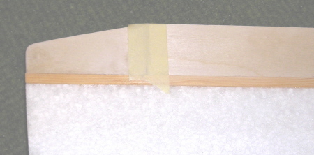
Fin
Assembly & Fitting
- Using round tile file (DIY stores), file half round recess in fin
leading and trailing edge to accommodate aerial tube (L. E.) and 3 mm
carbon rod (T.E.).
- Glue aerial conduit to leading edge of the fin using impact adhesive.
Tape in position using masking tape. Leave to dry overnight.
- Repeat above for trailing edge and 3mm carbon rod after contouring,
top and bottom of carbon rod (see plan).
- Cut 3.5 mm carbon rod to length. Insert in Fin and offer up to wing.
- Channel wing as required to accommodate carbon rod.
- When satisfied, align fin vertically and directionally and epoxy top
carbon rod in position. DO NOT allow epoxy to encroach on trailing edge
section.
- When epoxy sets turn wing upside down and epoxy bottom carbon rod
correcting any misalignment that may have occurred in the above operation.
- Chamfer rear faces of 1.5 mm ply fin stiffening plates. NOTE. There
will be a left and right hand.
- With fin in position, locate ply stiffening plates and superglue
in position. DO NOT use excessive superglue. The Fin is supposed to
be removable!
- Remove Fin from wing and contour exposed edges of ply plates to fit
Fin. Harden surface of ply plates with Superglue.
- Round ends of 6 mm triangular spruce fin location brackets (see plan).
- Fin assembly to wing. Check for correct alignment and superglue spruce
location brackets in position. Again DO NOT use excessive amounts of
superglue. The fin is not supposed to be a permanent fit.
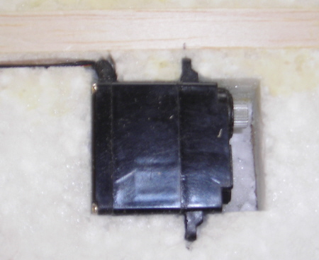
Building
Stub Fuselage
Note:
The components for the stub fuselage are 20mm longer than shown on the
plan. The model can either be built with a longer nose to reduce the amount
of nose weight required to achieve the correct balance point or built
as per plan.
- Superglue
4.5 mm balsa former to ends of 3mm ply sides.
- Superglue
middle former in position.
- Using
flat 180 grade wet & dry sanding block ensure base of fuselage is
flat and superglue 1.5 mm ply base in position.
- Using
spray impact adhesive glue EPP sides to fuselage and trim to size using
a sharp knife. Do one side at a time.
- With
wing weighted down on polythene sheet on a flat surface dry assemble
fuselage to wing. Bottom of fuselage should be flush with bottom of
wing and parallel to wing chord line, i.e. with a line drawn from bottom
of trailing edge to centre of leading edge.
- When
happy with alignment epoxy fuselage in place. Any gaps between fuselage
sides and wing can be filled with the slivers of EPP.
- Before
fitting the EPP fuselage bottom shape the rear section and then glue
in place using spray impact adhesive.
- Glue
EPP Top to 0.8 mm ply base and shape rear section as before.
- Cut fuselage
top in two and glue front section to fuselage.
- Fit nose
block.
- Trim
fuselage to shape with a sharp knife. Finish shaping using 180 grade
wet & dry.
Covering
- before covering use No Sanding Polyfilla to fill any hollows or crevices
in the wing and to smooth the transition from wing to rear spar. We
use a 12inch steel rule for this task. Leave to dry thoroughly before
attempting final sanding with 180 grade Wet & Dry.
- Spray model with impact adhesive and allow solvent to evaporate.
- We recommend using a polyester film, such as Profilm for the top
covering. We DO NOT recommend using Solarfilm or films made from a similar
plastic as they are more prone to stretching under tension. If using
a polyester film, apply the wing CW tape diagonally with the top and
bottom point in opposite directions, to increase torsional rigidity.
If covering in Profilm there is no need to overlap the CW tape. The
CW tape is applied lengthwise on to the fuselage. The CW tape will shrink
a small amount if ironed at the right temperature enabling a smooth
finish to be obtained on compound curves. DO NOT allow iron to dwell
in one spot too long or it will melt the EPP. When trimming the CW tape,
lubricate the knife with white spirit.
- Before applying the heatshrink film top covering lightly spray the
model with impact adhesive. Iron on films do not stick very well to
untreated CW tape.
- The normal technique, when covering with iron-on films, is to stick
and seal the film along the edges before shrinking the middle. When
covering EPP models we have found it easier to start in the middle and
work outwards. Sealing the edges is the last operation. If using the
iron on film for trim turn the temperature down to minimise shrinkage
and avoid a 'wavy' edge.
Flying
To achieve
the design performance of any model care must be taken in setting up the
controls and balancing the model both laterally (wing tip to wing tip)
and longitudinally (nose to tail). The Fast-bak is no exception. Control
movement must be symmetrical i.e. the same for both Elevons.
- Set the
controls to give the following movements for initial flights: Ailerons+/-15mm
Elevons +/- 6mm the Balance Point is in the middle of the Ballast Box
+/- 2 mm, Reflex 1.5mm.
- Adjust
balance to within recommended limits. This can be done by taping a hexagonal
shaped pencil along the bottom of the wing at the balance point and
resting the model on a flat surface clear of interference.
- Launching
the Fast-bak is easy. Place the thumb and second finger either side
of the fuselage just in front of the wing leading edge. The forefinger
is placed on the underside of the wing. This is important as the forefinger
ensures the model is launched in a level attitude and stops you pulling
the nose down and launching the model into the ground! The transmitter
is naturally help in the free hand.
- Remember
all aerobatic manoeuvres require energy to perform them. If the model
has insufficient speed it will fall out of the manoeuvre or perform
it half-heartedly. Vertical or near vertical dives are not an efficient
way to build up speed, 20- 30 degree dives are much more efficient.
Avoid sudden control inputs. In most cases all they do is scrub off
speed and lose height but they could also result in a violent 'flick'
roll. Try to fly smoothly with the minimum of control input as not only
do the manoeuvres look better but you will be able to perform more of
them before having to regain height. Try stringing manoeuvres together,
paying particular attention to positioning. Be creative and set yourself
targets for each flying session.
- If the
lift is very good or you are having difficulty penetrating into wind
try ballasting the model. This will increase penetration and help the
model maintain speed through manoeuvres. We have found the optimum ballast
to be about 250 grams. Over-ballasting any model will lead to a degradation
in its performance, often accompanied by a tendency to tip stall.
- The suggested
control settings are a starting point and can be adjusted to suit your
personal tastes. An indication that the balance point is about right
can be gauged by the amount of down elevator required for smooth inverted
flight and how the model recovers naturally from a dive i.e. sticks
in neutral and no pilot input. Please note moving the balance point
rearwards for racing will require less reflex and smaller control movements
with plenty of exponential (Positive for JR Negative for Futaba).
- If you
are using a computerised transmitter program Exponential on the Aileron
and Elevator controls. This will 'soften' the controls around the neutral
position and facilitate smoother flying particularly on the elevator
control.
- Fast-bak
will take a lot of punishment. It is excellent for building confidence
and will add another dimension to your flying but please remember if
you take a big enough hammer to anything it will break. The CW tape
used for covering also degrades in ultra-violet light so store the model
in a relatively cool place away from direct sunlight.
- The Modified
MH64 wing section is very efficient and performs well in light lift
so with good ballast selection Fast-bak will cope with almost wind /
lift conditions you are prepared to fly in.
- Finally
should you require further assistance or advice please contact us either
by letter, telephone, email or visit our website (http://www.phoenixmp.com)
where you will find useful information on sloping etc.
Happy flying
Stan Yeo
Fast-bak
061115
Footnote
For modellers
wishing to further improve the performance of the Fast-bak Andy Ellison,
a leading exponent of 60 inch pylon racing and well known magazine columnist,
has kindly written an addendum to these instructions giving tips on how
to make the Fast-bak a more competitive racing machine. Thankyou Andy.
Optimising
your EPP model for race use or high performance sport flight.
By Andy
Ellison
So you want
to turn your new PMP sport model into a full on competitive 60" race machine
do you?
Firstly
you'll have to sit mulling over your new pride and joy as it sits in it's
box, totally untouched and consider this carefully. If you want to produce
a model with a surface finish to rival a moulded carbon race machine,
and if you want to get the best possible performance from these simple
pieces of EPP foam lying before you, you're going to have to make your
mind up right now - before you build anything at all.
To obtain
a model capable of taking on the best; to optimise the airframe for maximum
speed and agility, it's going to have to be built clean, true, accurately
and slippery. You're going to have to consider modifying the model and
also the use of digital servos to obtain the necessary resolution as the
CG comes back to the optimised point for the airframe. You're going to
have to revise the radio installation, begin to use materials unfamiliar
to you and adapt to building techniques you may never have considered
before.
Sounds like
this is for you?
We'll look
at the digital servo thing first. As the CG comes further and further
back to optimise the speed potential of the airframe and produce tighter
turns, servo resolution plays a bigger and bigger part. On some 60" slope
racers the total travel of the elevators with a race tuned balance point
is no more than 2mm from full up to full down!
In order
to help achieve this good resolution across the entire stick movement,
very short servo arms (7mm or so) are used in conjunction with overlong
horns on the control surfaces. It is NOT OK to just rate the movement
down at the transmitter. This just wastes useful servo resolution…..
The use of
digital servos assists this optimal resolution and also ensures better
centring of the control surface after a movement to full deflection.
To turn
out a PMP model in race trim you may also like to consider some of the
following common modifications.
One of the
most obvious is the replacement of the supplied Correx fin with a shaped
balsa version. You can do this in a couple of ways. Either replacing the
Correx fin in it's entirety or by cladding it with balsa sides before
re-forming. If you'd like to keep the Correx but reduce the drag somewhat
you can remove some of the fluting around the edges and then bring them
together into a point. This can be retained by gluing or more commonly,
with fibre tape. The reduction in drag is audible in flight.
PMP models
often feature the fitting of a tube up the front of the fin which is utilised
to route the aerial from the receiver. Whilst this does dangle things
out in the breeze nicely it does nothing for the top end speed of the
model. If you are to optimise the aircrafts performance you need to tuck
the antenna away into the wing. A shallow scalpel cut snaking around the
foam of the wing will hide it nicely. You will need to do this before
you even think about covering the model.
A further
popular modification is the 'bagging' of the elevons with unidirectional
carbon fibre and epoxy to eliminate twisting and to finish them in a knife
sharp trailing edge. Bagging is achieved with the use of a vacuum pump
but good results can be achieved by pressing the carbon on against a plastic
or glass surface. Carbon cloth can be obtained at a number of outlets
in the UK but for best results the weave should be heavy (at least 200g)
or sewn tows should be used instead. The latter is more difficult to source
and has the appearance of straight, flat carbon tows sewn together by
clear monofilament or glass cloth. You will also of course need to fit
any ballast tube, ensuring easy access to the lead which may need to be
changed in a hurry at a race.
So with
these points in mind it's time to build the model. You should follow the
instructions implicitly varying only where you are considering a 'racing'
modification.
When you
have the radio gear installed and a bare model ready for tape you need
to fully consider the race tuned finish.
Spackle is
a term popularised on American forums and relates to nothing more than
interior wall filler. It is used to provide a glassy surface finish free
of the bumps EPP foam can leave under the model covering.
The product
I use for this task is Polycell quick drying filler from B&Q or similar
DIY outlets. When you pick up the large tub and think it's empty, you
have the right stuff.
To proceed
you must sand the wing in its entirety and make sure that the servos,
leads, receiver, antenna and battery (if it is housed in the wing) are
all in place. Bear in mind that you will need access to the receiver if
racing to facilitate removal of your crystal or switch frequency.
When you
are happy that the model is sanded smooth, liberally coat it in spackle
as if you were icing a cake. Go over everything except the receiver. That
includes the servo's which, if you have built the model correctly, may
only have their arms poking above the surface of the wing. Don't forget
to spackle over the ballast tube leaving easy access to the hole!
Now, quick
drying filler it may be but it's not going to set hard in 15 minutes in
your cold shed at the bottom of the garden. Get it in the house overnight
and let it really bake dry. Now you can cut it back with glass paper to
achieve a smooth finish. You will note that there may be some cracking
and that when sanded this first coat has only really filled the patina
of the foam. That's why you must now spackle the whole model once again.
This coat however can be much thinner, paying particular attention to
areas you might have missed properly first time around. Again you will
need to let this dry very hard overnight before cutting back to a fine,
smooth finish.
The model
is now at the stage where we need to use fibre reinforced tape (CW Tape).
Before this is applied some form of additional adhesive must be applied
to the surface of the wing. Many readers will probably be using foam backed
carpet spray adhesive. The kind that comes out of the can like silly string
and produces lumps under the covering if you spray from too far away.
A much better product (it's also more expensive) is 3M77 adhesive spray.
This again is a product used more in America than here but this glue is
available in the UK from an increasing number of outlets. It always sprays
in a controllable fine mist and dries much quicker than the carpet adhesive.
Some users may try permanent spray mount from art suppliers but in relation
to 3M77 it is quite weak.
When the
model is dry the tape can be laid onto the model in accordance with the
kit instructions. Taping on a biase of 45 degrees increases tortional
rigidity on some models and others often require no tape outside of the
servo arms. Follow the manufacturers lead but do not overlap the tape.
Instead the strips should be butt joined together to preserve the smoothness
of the surface finish.
The fibretape
we use has a release agent on the backing. How else would we ever get
it off the roll? This release agent must be removed before you progress
to the next stage of covering. This can be achieved by light sanding of
the tape. Just enough to get the agent to spall off in little balls but
not enough to sand through to the fibres of the tape. Go lightly until
the entire surface has a matt finish. The model is now almost ready for
final covering.
In my experience
Profilm has produced the best results for a racing finish. It does not
de-laminate like older Solarfilm and is generally tougher. Many pilots
have tried products such as gloss or Solartex but whilst this does contribute
more to the rigidity of the model it seems to produce slower flight. I
have no hard proof of this except the experiences of pilots flying different
models covered in both materials. I generally however use Solartex on
the fuselages of the models as it tends to wrap compound curves much better
than film.
PVC Tape
is not a serious finish for a racing 60" model. Great for combat but not
for speed. Many pilots however have started to achieve good results with
sticky backed 'Fablon' type material.
You must
also consider your chosen colour scheme. At a 60" race a distinguishable
colour scheme is a must. Not only for the flagmen but also for you as
pilot in the heat of a race. Consider this carefully as a yellow model
with red wing tips is sure to be one of many on the slope.
You also
seriously need to think about solid colours for each wing panel which
can be applied with one piece of covering. As we are applying the covering
to a foam model, the iron temperatures must be lower and the adhesive
may not grab as well. The scheme can be spruced up with sticky trim later
but the less edges capable of lifting, the better. Many pilots actually
tape over the leading edges with clear Sellotape Diamond after completion
to alleviate this further.
Before you
apply the covering one more light coat of 3M77 adhesive is required. When
this has set dry you will find that the film can be laid out and removed
for repositioning easily before ironing. A luxury not afforded to you
if you use a carpet spray adhesive. Take care to cover the undersides
of the model first to ensure that leading edge overlaps end up the right
way round and consider how you are going to hinge your control surface.
If your elevons are film covered you can also film hinge them. If however
you carbon bagged your elevons the best results can be achieved by hinging
with fibretape.
So now you
have a model ready for flight, but in need of race tuning in the air.
Generally if you push the CG back to the point where the model becomes
un-flyable and then shift it forwards slightly you'll be somewhere near
the money. Some plank type wings benefit from negative differential on
the elevons (i.e. - more down that up) to overcome the reflex and track
better through the turns and don't forget your control throws, especially
the elevator which should be set to avoid a high speed 'flick' if you
over pull in the heat of the moment.
When you
have the model optimised for yourself you're ready to race………
I hope you
can use the above notes to your advantage and look forward to seeing you
in the national leagues.
Andy Ellison
|